 Creating wall components
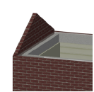
Wall components define the sections that make up a standard wall. For example, to indicate that a wall is made up of studs, inner drywall, outer sheathing, and siding, define a component for each of these items to illustrate their location. Wall components can be offset at the top or the bottom of the wall, individually constrained relative to the wall, the layer, or, for Vectorworks Architect and Landmark users, to story levels. Components can be textured, creating realistic section views and rendered views, as well as accurate wall supply estimates. If a material resource is used to define a component, the material typically provides the fill, texture, physical attributes, and construction information needed for drawings, renderings, and reports. The area and volume of wall components can be calculated in worksheets; see Worksheet functions.
The overall thickness of a wall is equal to the sum of its components. Component fill and pen style are only displayed in Top/Plan view (except for section viewports).
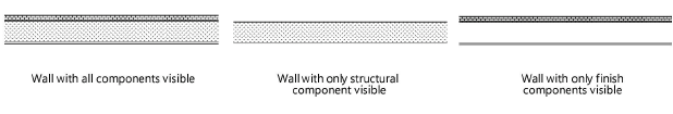
Wall components can be assigned to a class; this allows maximum flexibility since the component classes can be shown or hidden separately from the wall class. When a component is in an invisible class, its fill and lines are hidden. Invisible components on the interior and exterior of a wall cause the wall’s lines and fill to adjust to the visible components only, making the wall appear thinner than its actual width. This allows walls to show only their structural components, for example. If all components are invisible, the wall displays at its full thickness, without components. Set walls to display only visible components from the Object Info palette (see Wall properties).
The Auto-display detail levels for design layers preference can be used to show or hide wall components based on scale; see Hiding wall components.
Use the Eyedropper tool to copy wall component settings from one wall to another (see Transferring attributes).
Curtain walls do not have components.
To define a wall component:
Do one of the following:
To define a component while a wall or wall style is being created, open the Definition tab of the Wall Preferences dialog box (see Drawing walls).
To define or edit wall components for an existing, unstyled wall, or to edit the components’ top and bottom heights for styled walls, select the wall and click Components on the Object Info palette to open the Wall Components dialog box.
The Components list in the Wall Components dialog box is identical to the list on the Definition tab of the Wall Preferences dialog box. For a description of the parameters in the Wall Preferences dialog box or the Wall Components dialog box, see Standard wall preferences.
Below the Components list, click New to create a new component or select a component to edit and click Edit.
The Wall Component Settings dialog box opens. Specify the component thickness, name, and parameters.
Click to show/hide the parameters.Click to show/hide the parameters.
|
Parameter |
Description |
|
Definition |
|
|
Name |
Provide a name for the component, which displays in the Components list in the Wall Preferences dialog box |
|
Function |
Specifies a function for the component, to be included in IFC exports |
|
Class |
To control appearance and visibility, select a class from the list of classes present in the drawing, or create a new class. Select <Object Class> to place the component attributes in the same class as the wall object. Wall component class textures are set from the Textures pane of the Edit Class(es) dialog box (see Concept: Applying textures by class). |
|
Use material |
Uses a material resource for this component; select a material from the Resource Selector. The Lambda, Fill, and Texture settings are set to the material’s settings, and the Lambda and Fill parameters are disabled. |
|
Lambda |
Indicates the lambda value for the wall component. The lambda value participates in energy analysis calculation parameters for the wall component. Vectorworks Architect is required to conduct an energy analysis; however, energy-related parameters can be specified here for informational purposes. |
|
Look Up |
Opens the Look Up Lambda Value dialog box, to specify the lambda value. The value can be calculated based on the U-value or R-value and the component thickness; the calculated value is displayed. Alternatively, lambda values are provided for typical component elements; select the component element with its predefined lambda value. Filter the displayed list by entering a filter term; click Edit List to enter the value manually. |
|
Thickness |
Specifies the component’s thickness; the thickness of a wall is the sum of its components. A component must have a thickness greater than 0. |
|
Component Top |
|
|
Relative to wall |
Sets the top of the component relative to the top of the wall |
|
Relative to story (Architect or Landmark required to set to story levels) |
Select the vertical reference that determines the top of the component from the Top Bound list. The Layer Wall Height or Layer Elevation value is set by the design layer (see Setting design layer properties). Additional options are available for the Vectorworks Architect and Landmark products. The top of the component can be bound by one of the story levels defined for the story or the story above it. Select the level from the Top Bound list. By setting the top of the component to a level type, if the elevation of the associated story changes, the height of the component changes automatically to match. |
|
Top Offset |
Specifies an additional offset distance for the component from the top of the wall |
|
Follow top wall peaks |
The component follows the wall peaks at the top of the wall |
|
Component Bottom |
|
|
Relative to wall |
Sets the bottom of the component relative to the bottom of the wall |
|
Relative to story (Architect or Landmark required to set to story levels) |
Select the vertical reference that determines the bottom of the component from the Bottom Bound list. Layer Elevation is the only option available unless the Vectorworks Architect product is installed. Additional options are available for the Vectorworks Architect and Landmark products. The bottom of the component can be bound by one of the story levels defined for the story or the story below it. By setting the bottom of the component to a level type, if the elevation of the associated story changes, the height of the component changes automatically to match. |
|
Bottom Offset |
Specifies an additional offset distance for the component from the bottom of the wall |
|
Follow bottom wall peaks |
The component follows the wall peaks at the bottom of the wall |
|
Always auto join in Capped Join mode |
When selected, the components of automatically joined walls are always joined in a capped configuration, even if the components have the same fill. When deselected, the components of automatically joined walls are joined in a mitered configuration if they have the same fill and in a capped configuration if they do not. |
|
Master Snap Points |
Sets the location of any master snap points for the component. A master snap point takes priority over other object snap points; add master snap points to the sides of components where priority snapping is desirable. For example, when dimensioning walls, you may wish to easily place the dimension witness line on the left side of a specific component. See Concept: Snapping indicators. |
|
Left side of component/ Right side of component |
Select the option to enable a master snap point location on either side or both sides of the component |
|
Fill |
Specifies the component appearance in section views. If the component uses a material, the fill is set to the material’s fill, and the controls are disabled. Otherwise, select a fill style, or Class Style to set the fill attributes by class. Depending on the Style selected, select a color, pattern, or resource (hatch, image, gradient, tile). Use a tile fill with Fit to Wall selected to represent insulation fill. See Defining and editing tiles. |
|
Texture |
Applies the selected texture to the component. If the component uses a material, the texture is initially set to the material’s texture, but this can be overridden. Class Texture sets the component to use the texture specified by the component’s class; see Concept: Applying textures by class. If Texture is chosen, this setting overrides the object material and/or class texture; select a texture from the Resource Selector. The Object Info palette Render tab has additional texturing controls for existing objects; see Managing object textures from the Object Info palette and Textures on objects with components. Textures applied from the Object Info palette override the textures set here unless the texture is set by style. |
|
Left Pen/Right Pen |
Select a pen style, or Class Style to set pen attributes by class. Depending on the Style selected, select a color, pattern, or line type resource. |
|
Thickness |
Select the line thickness; to use a custom thickness, select Set Thickness from the line thickness list (see Line thickness attributes) |
|
Make All Attributes By Class |
Sets all fill, pen, and texture attributes by class, except those that come from a material |
|
Remove By Class Settings |
Removes all class settings for fill, pen, and texture attributes; does not affect material definitions with attributes set by class |
After you click OK, the wall’s Overall Thickness value changes to reflect the changes to the components. As components are defined, they display in the preview. Click and drag a component in the # column to change its order. Click in the Core, Insert Loc., and Offset columns to set components as described in Standard wall preferences.
